CALIBRATION
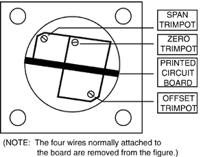
Refer
to Figure 7-1 for the location of the span, zero, and offset trimpots.
Required equipment and conditions:
a) Long small-bladed screwdriver
b) Known low RH environment (5 to 25%)
c) Known high RH environment (75 to 95%)
d) Known temperature environment (0 to 100░C - not liquid)
1. Remove the four flange screws for HX10 Series; remove
case cover screw for HX20 Series |
 Figure
7-1. Trimpot Locations
|
2. For HX10 Series, gently pull on the four wires to stretch them
out to gain access to the trimpots. The adjustments are available on the
HX20 Series via screw cover removal.
3. Place the sensor in a known low RH environment. Adjust the zero
trimpot to obtain the corresponding current or voltage output as appropriate.
4. Place the sensor in a known high RH environment. Adjust the
span trimpot to obtain the corresponding current or voltage output as
appropriate.
5. Place the sensor in known temperature environment and adjust
the offset trimpot to obtain the corresponding current or voltage output
as appropriate.
6. Gently "stuff" the four wires back into the long tube of the
transmitter by curl-ing in a circular pattern.
7. Replace the cover with the screws.
MAINTENANCE
If the transmitter is operated in a dusty environment, the protective
sensor filter, if clogged, may be removed for cleaning. Unscrew filter
and gently blow com-pressed air through screen. If necessary, use a soft
brush to remove lint from the sensors.
If the sensors are subjected to 100% condensation, they must be dried
to obtain correct readings. There is no permanent calibration shift, nor
is recalibration nec-essary if 100% condensation occurs. It may take from
24 to 48 hours for the transmitter to return to calibrated accuracy.
ACCESSORIES
The following accessories may be obtained by contacting our sales department
at the number listed on the inside cover of this manual.
|
PART
NO.
|
DESCRIPTION
|
|
PT06F-8-4S
|
Mating
Bendix 4-pin connector for the HX12 |
|
U24Y101
|
24VDC,
1000mA, unregulated power supply |
|
PSU-24B
|
24VDC,
200mA, unregulated power supply |
|
HX10-DM
|
HX10
Series Duct Mounting Kit |
DUCT
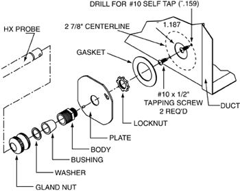
MOUNTING INSTRUCTIONS
The following instructions describe how to mount the HX10 Series Transmitters
in a duct using HX10-DM Duct Mounting Kit.

1. Mark and cut out center hole for probe clearance.
2. Mark and drill 2 holes for mounting screws.
3. Apply gasket to plate.
4. Pass body through plate and secure with locknut.
5. Attach plate assembly to duct wall with screws.
6. Pass probe through gland nut, beveled washer and rubber bushing
into body.
7. Adjust probe depth as desired.
8. Secure probe by tightening gland nut (finger tight).
|